Using VDATP with the web GUI
VDATP can be controlled using a web GUI or through a REST API. The web GUI is served by the Raspberry Pi. The web server can be started by SSHing into the Pi and typing in the following
cd vdatp; node build
Note that the environment variable VDATP web GUIVDATP_CONFIG_DIR needs to be set to point to the directory ~/vdatp/build/condig - this will likely have been set for you already. Once the server has been started, you can open the webpage at {ip address}:3000. This will open the following page: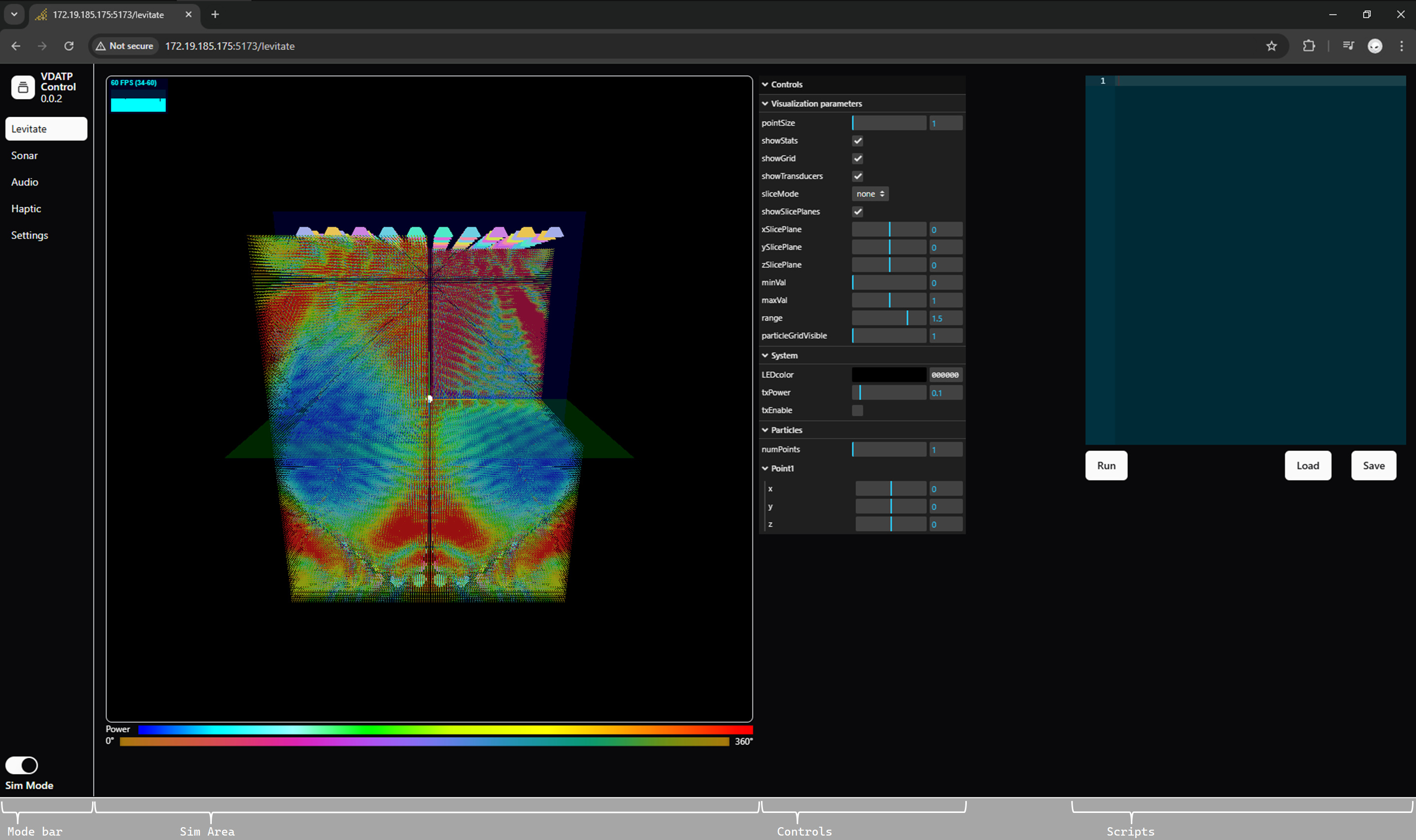
The parts of the GUI are as follows:
- Mode Bar allows you to access various modes of operation of VDATP. At the time of this writing, only
Levitateis enabled. You can also access theSettingstab, where you can upload a FPGA configuration file. TheSim Modebutton disables communication to the units and can be used to try out new scripts or settings with affected the connected unit. - Sim Area displays a simulation of the acoustic fields. You can rotate and zoom into the simulation using mouse controls.
- Controls these can change either the simulation visualization parameters or directly send commands to VDATP. More on this below.
- Scripts allows you to write simple scripts to perform a set of actions in VDATP. More below.
Let’s levitate!
You first need to program the FPGA and to do so you need to acquire the FPGA programming file (called an RBF file). You can download the latest release here. Once you have the file, start up the GUI and select Settings in the Mode bar. Under the FPGA Parameters card,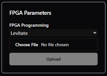
Choose file button to select the RBF file and then press Upload.
Once that is done, return to the Note that the LEDs can generate a lot of heat (enough to melt the enclosure) and have been set in hardware to limit the amount of power they can consume. In general, they should be able to operate at reasonable light levels but you may want to check the LED mounts to ensure they aren’t getting too hot.Levitate screen. Make sure Sim Mode is off. You can verify that the FPGA was programmed correctly by setting the LED color to something other than black.LED heat generation
Once communications with the system is verified, you can then click txEnable which will enable the transducers. You can use the sliders under Point1 to issue a positioning command (e.g. move X to some value and then back to 0). You may hear the array emit a high pitch whine that changes as the focus point is moved - this is normal
Hearing protection
A Bit Embedded makes no claims as to the safety of this apparatus. Appropriate hearing protection should be used.You should now be able to levitate a small foam ball or water droplet by placing it at the focus point of the array: coordinate (0, 0, 0) is exactly in the center of the array, centered between the top and bottom units. You can move the particle by clicking on the numbers next to the coordinate sliders and the pressing the up and down arrow keys - the sliders move the focus point too quickly and the particle tends to lose the focus if it is moved via the sliders. You can use the Note that transducer drivers can produce a lot of heat at higher voltage levels. It’s recommended you use only the transducer power required for the experiment and set it to a lower value (or disable the transducers) when not in use.txPower to change the voltage the drivers apply to the transducers from about 9V to 36Vpp. Generally, low txPower (under 0.3) works great.Transducer driver heat generation
Simulation
Notice that as you use the controls to move the particle, the simulation is updated to show the pressure waves and transducer phases. The simulation grid has a resolution of 1mm, which should easily run on most PCs equipped with even an old GPU. The simulation controls are as follows:
- pointSize increases the apparent size of the visualized grid points (try it to see)
- showStats displays a Statistics box that shows the current Frames per Second, milliseconds to render the frame, and MB of allocated memory. Click on the stats box to change what is being shown.
- showGrid displays the simulation grid
- showTransducers displays the transducers
- slideMode allows the user to visualize slices through the grid by changing the
xSlicePlane,ySlicePlane, andzSlicePlanesliders. IfsliceModeisnone, all the slice planes are active and you can carve out a rectangular section of the grid to see inside it. Selecting a different slice mode literally shows just a thin slice of the grid. - showSlicePlanes displays the slice planes (they’re very faint and the same color as the axes)
- minVal, maxVal and range work together to increase the contrast of the visualization. Note that grid points with power less than
minValare not displayed, making for a cleaner display. - particleGridVisible more details below
Levitating multiple particles
This version of VDATP can levitate multiple particles by driving the individual particles through time multiplexing the arrays. For each focus point, the transducer phases are calculated independently and these sets of phases (one for each point) are sent to the FPGA. The FPGA then switches from one set of phases to the next in a round-robin fashion every 1/40000 of second. Currently the system supports up to 4 points, set by numPoints. particleGridVisible selects which particle grid is being shown.
Scripting
Simple scripts can be written to automate experiments. At the moment, this is done with a custom scripting language but will be migrated to Javascript in a future release. A script looks like this:
sys.color(0x10, 0x10, 0x10)
sys.txPower(0.2)
sys.numParticles(2)
sys.timeScale(2)
sys.txEnable(1)

a.home(10, 0, 10)
b.home(-20, 0, -20)

executeAndWait()

a.moveTo(10, 10, 10)
a.moveTo(10, 0, 10)
a.moveToHome()

b.moveTo(-30,-23,-23)
b.moveToHome()

executeAndLoop()

a.moveToHome()
b.moveToHome()

execute()
There are three types of commands: system, particle and execute.
System commands control the overall systems as follows:
sys.color(r, g, b)- sets the LED colors to (r, g, b). Values can range from 0 to 255, hex or decimal.sys.txPower(power)- set txPower to power. Valid values range from 0 to 1.sys.numParticles(num)- set the number of particles to num. Valid values range from 1 to 4.sys.timeScale(scale)- allows the simulation to run slower by the factor scale. Valid values are integers 1 or greatersys.txEnable(enable)- enables (1) or disables (0) the transducers
Particle commands start with the letters {a, b, c, d}, representing a specific particle. Each particle has the concept of home which sets the particle position to a specific position instantaneously. All other particle commands are used to identify a specific location to travel to, which is used used to build a path of intervening particle positions. These paths can then be executed.
P.home(x, y, z)- set the particle home position and move the particle to that position instantaneously when executed.P.moveTo( x, y, z)- generates a path for the particle to move in a straight line to the point (x, y, z)P.moveToHome()- generates a path for the particle to move in a straight line to the previously set home point, or (0, 0, 0 ) if no home position has been set
Execute commands run the current particle paths. The paths are erased when the execute command finishes.
executeAndWait()- causes the particles to execute their paths once and then wait for the user to press theContinuebutton that will appear under the text editor. This is generally used to set a home position for the particles allowing the user to then insert particles (e.g. foam balls) into the sound field.executeAndLoop()- causes the particles to continuously execute their paths until theBreakbutton is pressedexecute- runs the paths a single time and continues script execution
Updating the software
Both the GUI and Raspberry Pi software can be updated using the following procedure on the Pi:
cd ~/vdatp
wget https://github.com/danfoisy/vdatp2_gui/releases/latest/download/build.tar
tar xzf build.tar
cd build
npm install --omit=dev
cd ..
node build