Assembling VDATP
Your system consists of the following parts: VDATP kit of parts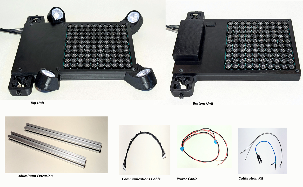
Assembly
To assemble, you will need a hex key for M3 bolts.
- Take an aluminum extrusion and insert it into one of the mounts on the bottom unit. You may need to loosen the bolt on the mount to allow the metal T-Nut to slip into the extrusion slot.
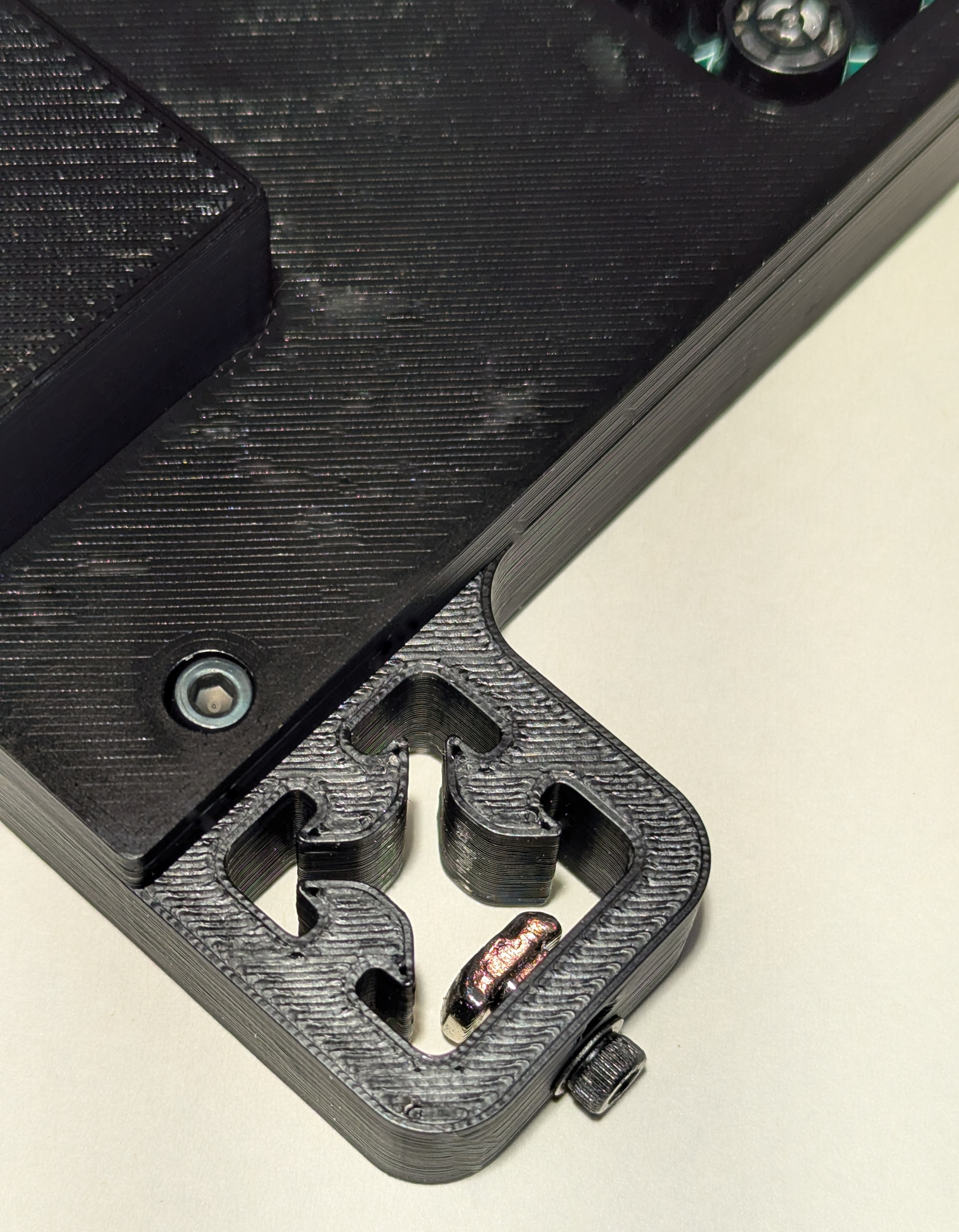
- Align the bottom of the extrusion with the bottom of the unit and tighten the bolt snugly. Repeat on the other side.
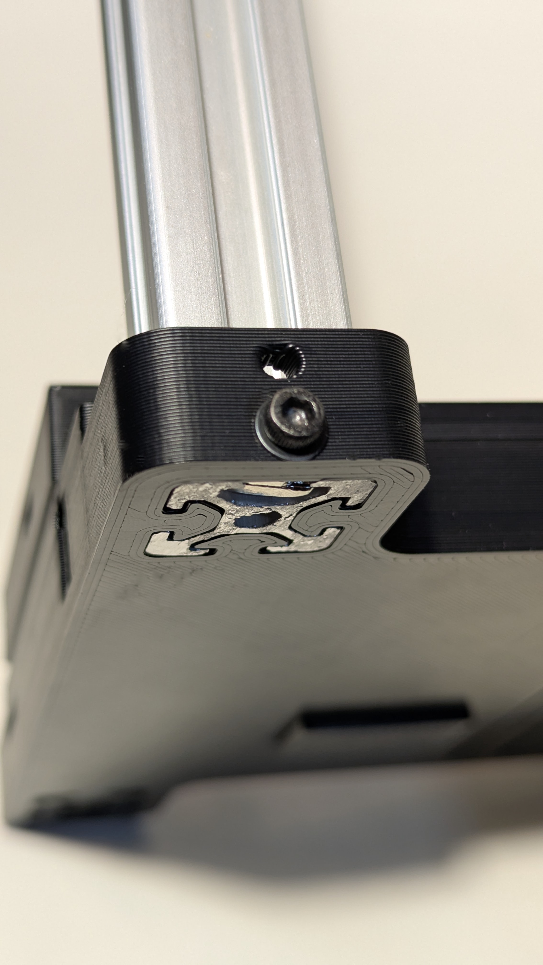
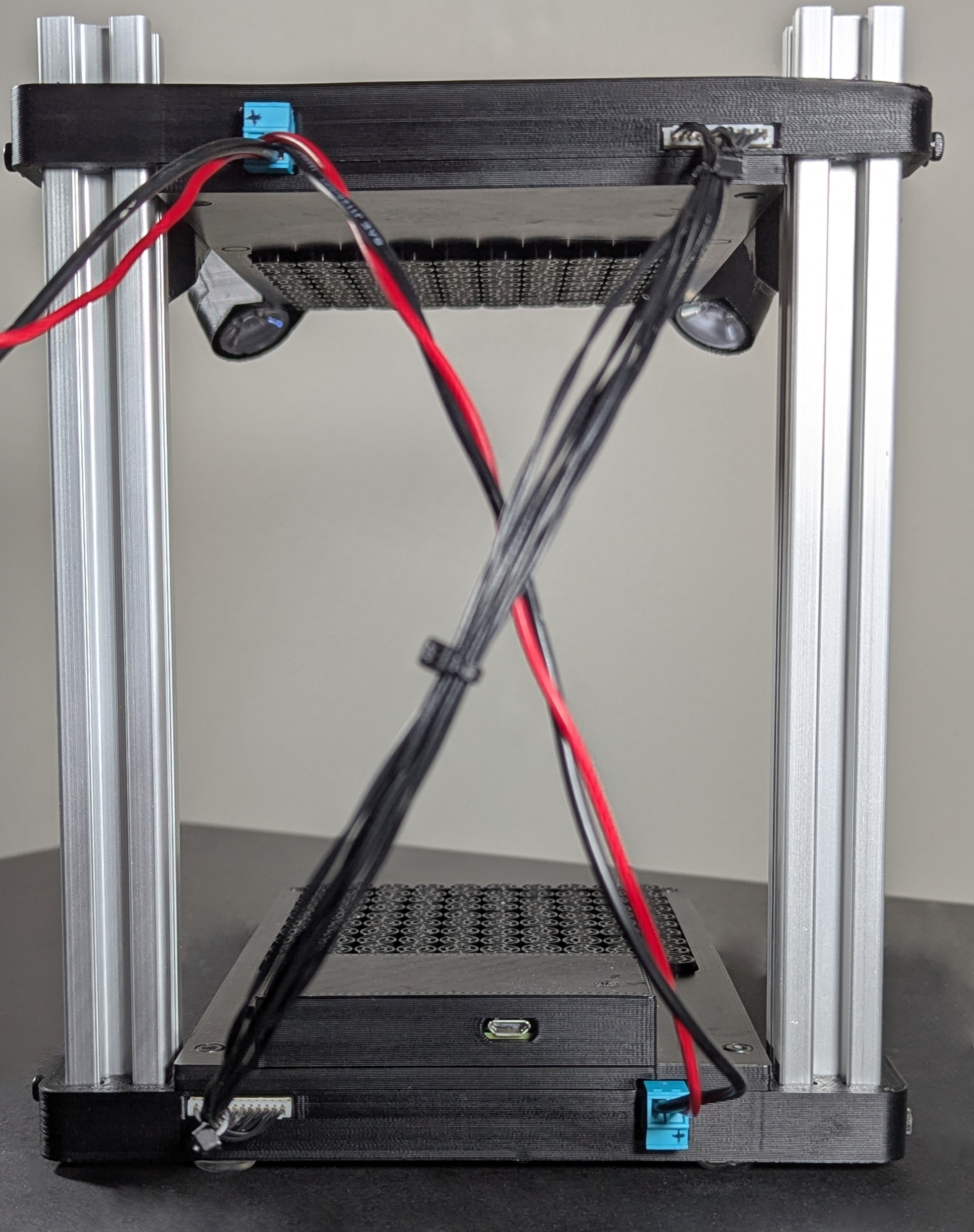
- Now take the top unit and slide it onto the two aluminum extrusions. It’s a tight fit so you may need to squeeze the aluminum extrusion together a bit to get them to fit into the mounting slots. Do not tighten bolts.

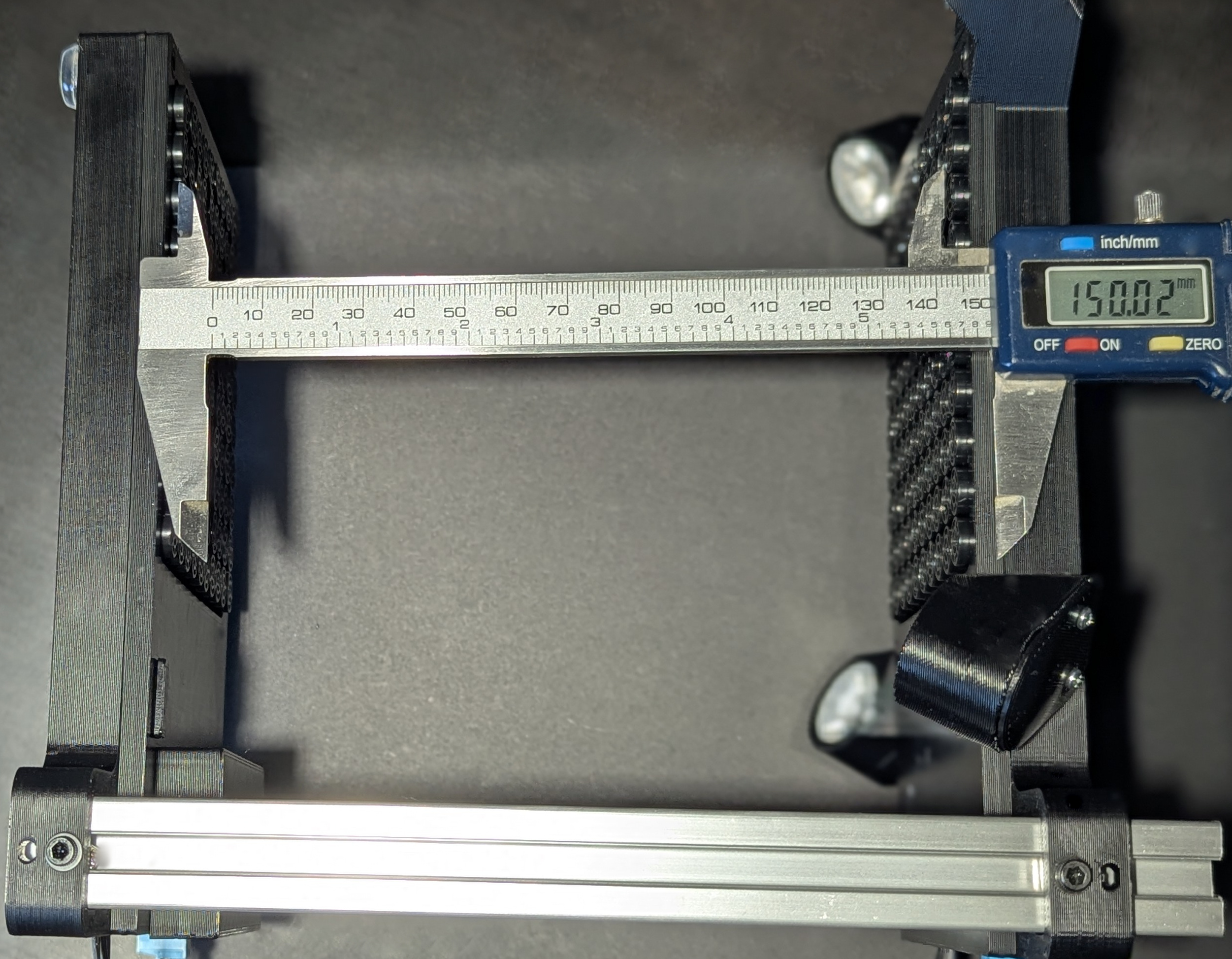
- Using calipers or ruler, adjust the height at the bottom of the top unit so that it is 150mm from the top of the bottom unit. Once the height is adjusted, you can tighten the bolts.
- Insert one end of the communications cable (doesn’t matter which) into the communications port of either unit. The connector is keyed so that it only fits in one orientation. The fit is quite tight and you may need to use a small flat head screwdriver to ensure the connector is fully seated. Do the same with the other side of the cable and the other unit.
- Insert the power cables - again the connectors are keyed.
- Connect the power cables to an adjustable power supply - 20V with a current limit of 2A works well.
At this point, you must decide how you wish to connect with the system. There are two ways:
- Wifi
- USB
Wifi set up
Note that you can also perform Wifi setup by following the instructions under USB setup, SSHing into the Pi and using the sudo raspi-config utility to configure Wifi.
- Remove the Raspberry Pi cover from the bottom unit
- Carefully remove the SD card and insert it into a PC (Windows/Mac/Linux)
- Follow the instructions here to create a
wpa_supplicant.conffile and load it on the SD card. - re-insert the SD card into the Pi and replace the cover
- The IP address will likely be dynamically set by your Wifi router and you’ll have to examine the router logs to determine the address (should be displayed as
VDATPin the logs).
USB set up
This will use the Pi’s USB connection to emulate an Ethernet port. This means you’ll be able to use SSH into the PI as well as see the hosted control webpage and use the REST and websocket APIs. The Windows driver for this is a little flaky and can cause a BSOD :(
Warning
Only use the supplied USB cable. This cable has been modified to disconnect the +5V wire. If you use a standard USB cable, it will damage the board. The next version of the boards will have a fix for this.- Connect the supplied USB cable between a PC
- Follow these instructions for Mac or Windows but using
10.20.30.41for the IP address and10.20.30.1for the Router/Gateway - The IP address of the PI is static and set to
10.20.30.40
Turning it on (and off)
- Turn on the power supply - at idle with no FPGAs programmed, the current will be about 0.44A. The Raspberry Pi activity light will be visible through a small hole in the Pi Cover.
- After about 30s, you can try to ssh into the Pi using either
[email protected]orvdatp@{Pi IP address}. The password israspberry. Feel free to change the password :) - To shutdown the system properly, it is highly recommended to issue the command
sudo shutdown now
to the Pi and wait for the activity LED to stop blinking so as to prevent any potential file system corruption. You can also set the file system to read-only through raspi-config to prevent file system corruption but that’s a bit of a pain when trying to update the system.